Network Shape
The "shape" of the whole network
for a simulation is determined by:
- the position of the Nodes which are defined
- the data specifying the Track sections which
link the Nodes
Node Co-ordinates
Every Node is assigned values for its
Row and Column co-ordinates. This applies to those which
are within the visible simulation area, as well as those
which lie outside this area, to the left and/or right
of the visible area. Node co-ordinates must be unique,
i.e. 2 Nodes cannot have the same position.
- row - a positive value defining
the Node's vertical position, increasing in value from
"top" to "bottom" of layout.
- col - a positive value defining the
Node's horizontal position, increasing in value from
"left" to "right" of layout. Since
the network usually includes Nodes to the left of the
controlled area, the values used need to allow for these
to be defined with positive values.
Selecting appropriate spacings between
Nodes is something of an art, and there are no wrong
or right ways to do it. However, it is suggested
that you keep to the following guidelines which have
been found to work well:
- Spacing of adjacent horizontal parallel
tracks: use multiples of 8 for the Node.row
values.
- Crossovers and other diagonal tracks: increment
the column value by the same absolute amount
as the row value, e.g. if row difference = 8,
column difference = +8 or -8 depending on the
required slant direction.
- Do not try to space Nodes and Tracks too
closely or you may have difficulty fitting other
components of the display into the restricted
space available.
- Allow for the widths of Train
Describers (11 columns) and point and signal
Labels (8 columns for 3-digit labels).
- Nodes do not need to be positioned "to
scale" compared to the real layout. Although
you will want to give some clues as to the length
of track sections, it is best to use (in effect)
a larger scale for areas of complicated trackwork
and a smaller scale for long sections of plain
track.
Track sections
Each track section is a link between 2
Nodes, defined by values of node and nodeto.
These should be specified reading from left to
right of the layout or, for vertical links, from top
to bottom.
Limitations
- Nodes of type B (buffer stops), F (fringe),
P (points), Q (platform end), S (signal), and Y (yard
entrance) must be located on horizontal sections of
track.
- The data structure does not
cater for single or double slip
points.
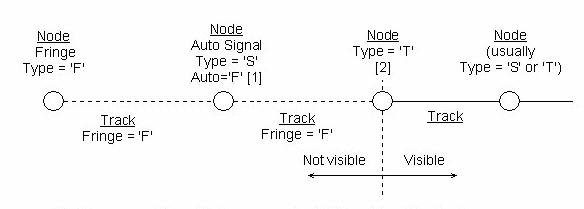
Fringes
|
[1] One or more Signal Nodes as required.
All must be Auto signals.
|
|
[2] This Node can be
omitted if you wish the visible track to extend to edge
of the layout window.
|
|
See
below for bidirectional fringes (e.g.
single
track branch lines).
|
|
The Data Builder software
can automatically generate the data for
fringes, so you only need to specify the Fringe Node
(Type 'F') and one Track record linking
to it.
|
Bidirectional Fringes (Single Lines)

|
[1] One or more pairs
of Signal Nodes (one for each direction)
as required.
All must be Auto signals.
|
|
[2] This Node can be
omitted if you wish the visible track to extend to edge
of the layout window.
|
|
The Data Builder software
can automatically generate the data for
fringes, so you only need to specify the Fringe Node
(Type 'F') and one Track record linking
to it.
|
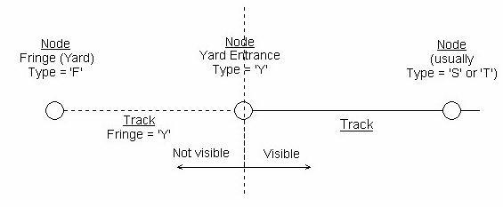
Yards
|
If you do not supply the
data for the Fringe Node and Track, the
Data Builder software will automatically
generate it, i.e. only the Yard Entrance
Node needs to be specified. This will also
ensure that the required Route records are
created.
|
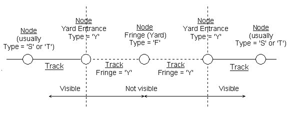
Yards (multiple entrances)
|
If a Yard has 2 entrances/exits,
they should share the same Yard Fringe Node,
as shown above.
|
Points and Crossovers
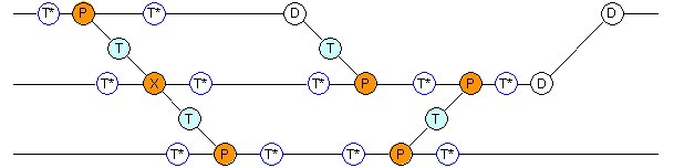
The nodes are labelled with the required
Type value. Nodes marked T* are not required if
there is another node of type B, D or S in a similar
position. Any 2 adjacent nodes marked T* could be combined
into one, depending on track circuiting requirements.
Scissor crossing
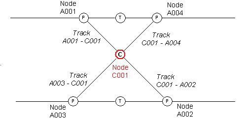
The nodes are labelled with the required
Type value. Note the use of the Type C node.
Double slip points
A sketch of the arrangement of nodes and lever numbers has been kindly provided by David Wilkinson.
Flyovers
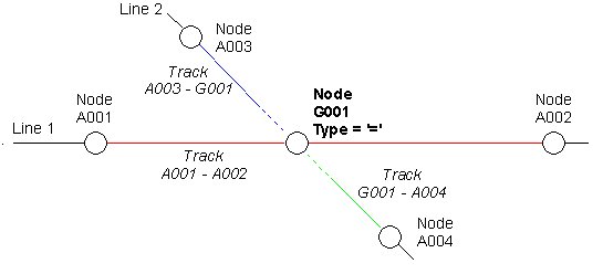
Line 1 crosses above Line 2 at Node
G001, without physical connection

Line 2 crosses above Line 1 at
Node G001, without physical connection
|
