PC-Rail Data Values
This page provides further details on the usage of many of the data fields,
and the permitted values.
For a detailed explanation of the data
defining the shape of the network and visual display positions see
Network Shape and
Layout Display.
All data defining direction, as detailed in
the tables below, uses the following conventions:
| Value |
Direction (as the layout is viewed)
|
Notes
|
|
1
|
Left to Right
|
Or (where applicable): Top to Bottom
|
|
-1
|
Right to Left
|
Or (where applicable): Bottom to Top
|
|
0
|
Either
|
Where this value is permitted.
|
Node data
|
Node Types
|
| Type of node |
Value of node.type |
Value of node.node |
No. of tracks |
Notes
|
|
Unique 4-character code.
The following conventions are recommended:
|
|
Buffer stops (lever xyz)
|
B
|
Bxyz
|
1
|
[1]
|
|
Diamond crossing (unswitched)
|
C
|
C999 (or any)
|
4
|
[4]
|
|
Deviation |
D |
999A (or any) |
2 |
[4]
|
|
Fringe
|
F
|
Z### (or any)
|
1
|
[2]
|
|
Points (lever xyz)
|
P
|
xyzA |
3
|
[1][4]
|
|
Platform end
|
Q
|
Q999
|
2
|
|
|
Signal (lever xyz)
|
S
|
Sxyz
|
2
|
[1]
|
|
Track circuit joint
|
T
|
T999 (or any)
|
2
|
[4]
|
|
Crossing (lever xyz)
|
X
|
xyzA |
4
|
[1][4]
|
|
Yard entrance (lever xyz)
|
Y
|
Yxyz |
2
|
[1][2]
|
|
Bridged crossing (no connection)
|
=
|
G999 (or any)
|
2
|
[3]
|
|
Where 9 = numeric
character, A = alphabetic character,
# = any character,
xyz = numeric
characters (typically the same as the lever
number - see below).
|
|
Notes:
[1]
See Lever numbers below.
[2] Fringes and Yards:
more details.
[3] Flyovers:
more details.
[4] Points, Crossovers and diamond crossings:
more details.
|
|
Lever numbers
|
|
Nodes which are used to define routes
(e.g. signals, yard entrances, buffer stops),
or controlled duing signalling operations
(e.g. points) are assigned a Lever number.
This is defined by a value in the node.lever
field. No value is required in this field
for other node types.
Lever numbers consist of between 3 and 5 alphanumeric
characters (normally numeric values only
are used). Leading zeros should be used
for lever numbers less than 100 (e.g. 001).
In the visual display the lever number is
shown on the relevant node label, with leading
zeros omitted.
In almost all cases, the following default
conventions are sufficient:
|
| Type of node |
Value of node.type |
Node identifier (value of node.node)
|
Default lever number
|
Notes
|
|
Buffer stops |
B
|
Bxyz
|
xyz
|
[1]
|
|
Points
|
P
|
xyzA, xyzB
|
xyz
|
[2]
|
|
Signal
|
S
|
Sxyz
|
xyz
|
|
|
Crossing
|
X
|
xyzC
|
xyz
|
[2]
|
|
Yard entrance
|
Y
|
Yxyz
|
xyz
|
|
|
Where x, y, z = any characters
(normally numeric).
|
|
[1]
Use zero value if no lever number to be
displayed (e.g. "buffer stop"
for facing trap-points).
[2] Crossovers: in general, their
nodes should be numbered
in pairs, e.g. 920A and 920B would
define the 2 "ends" of the crossover. Where a crossover
crosses another running line, use additional
suffix letters, e.g. 920C.
|
|
Generally you should leave the node.lever
field empty, so that the Data Builder software
will automatically assign the lever numbers
according to the above scheme. Subsequently
you can edit the data to provide any Non-default
values which you might require.
Note that lever numbers must be unique
- take care in numbering nodes or you could
inadvertently get duplicate lever numbers.
For example, nodes 001A, S001 and B001 would
all be allocated default lever number
001.
|
|
Additional
data fields: Signal nodes (and a few other
minor uses)
|
| Field |
Data |
Value |
Meaning
|
Notes |
|
subtype
|
Node subtype
(Signal type)
|
1
|
2-aspect
|
(R/Y)
|
|
2
|
2-aspect
|
(R/G)
|
|
3
|
3-aspect
|
(R/Y/G)
|
|
4
|
4-aspect
|
(R/Y/YY/G)
|
|
0
|
Distant/Repeater |
(Y/G) [2] |
|
D
|
Shunt signal
|
|
|
L
|
Limit of Shunt
|
|
|
R
|
Points to be initially shown in "Reverse"
position.
|
Applies to Node Type 'P'. [1]
|
|
subsid
|
Subsidiary aspect
|
C |
Signal has subsidiary aspect
|
Applies only to main signals
(subtypes 2/3/4)
|
|
(empty)
|
No subsidiary aspect
|
|
|
auto
|
Automatic working code
|
F
|
Automatic
|
|
|
A, B, C ...
|
Semi-auto
|
Value = suffix of route identifier set
by 'A' button.
|
|
X
|
Automatic
|
On bidrectional lines
|
|
(empty)
|
No auto working
|
|
|
rundirec
|
Running direction to which signal
applies
|
1 or -1
|
|
|
| prow |
Display row |
(Use value -1 to suppress display)
|
| pcol |
Display col |
|
prow2
|
Display row (2)
|
For "platform starter" signals: position
of TRS button. [3]
For semi-auto signals: position
of ''A' button.
If both uses are required, define the 'A' button in the miscobj data file (q.v.)
|
|
pcol2
|
Display column (2)
|
|
Where
# = any character.
[1] The software regards "Normal" as the straight-ahead route at points, and "Reverse" as the
diverging route.
[2] Distant/Repeater signal, aspect dependent on that of the next signal ahead. Routes should be defined, one from the signal in rear and one to the signal ahead. In addition a multiroute is required containing both of these routes.
Aspects displayed by such signals are controlled by the software and not by the operator. The prow2 and pcol2 fields should be empty,
as should the auto field except where the value 'X' is required for fringes on a bi-directional line.
|
|
The software uses standard
British multiple aspect signalling. There
is a lot of information on this at:
www.railway-technical.com/sig-uktypes.shtml
|
Track data
| Field |
Data |
Value |
Notes |
|
maxspeed
|
Maximum permitted speed
|
Integer >0
|
In m.p.h.
|
|
fringe
|
Fringe track indicator
|
F
|
Track outside controlled area. Not displayed.
More details
|
|
Y
|
Track within Yard. Not displayed.
More details
|
|
H
|
Hide track (other than fringes and yards)
|
| 1, 2, ... |
Route is part of Line worked as OTOL [set values to '1'; if there are other separate OTOL lines, use '2', etc.]
|
|
(empty)
|
Other track
|
|
tc
|
Track circuit identifier |
I
|
Data Builder software has a facility to automatically
generate this data as a first approximation.
Track records with the same TC
identifier must be contiguous. |
|
scale
|
Scaling factor
|
Numeric
|
Calculated as length1/length2, where
length1=simulation length of track
[1],
length2=real world length in miles
x 80.
Programs known to work for values between
0.20 and 6.00.
|
|
grad
|
Gradient [2]
|
0
|
(Default) = Level track
|
|
Integer n >0
|
Rising at 1 in n.
|
|
Integer n <0
|
Falling at 1 in n.
|
|
[1] As defined by Node.col values of the
2 Track ends (or Node.row values for vertical track sections).
[2] Use of this
field not currently implemented in simulation
software.
|
Platform data
| Field |
Data |
Value |
Applies to
|
Visual display of Platform
|
|
plat_type
|
Platform type code
|
(empty)
|
All trains
|
Yes
|
|
F
|
Freight trains [1]
|
No
|
|
P
|
Passenger trains [1]
|
Yes
|
|
S
|
All trains
|
No
|
|
T
|
All trains: timing point only, no stop permitted.
[2]
|
No
|
|
|
|
|
Meaning
|
|
d_showhi
|
Display position
|
true
|
Above track
|
Where applicable. [3]
|
|
false
|
Below track
|
|
nocheck
|
Suppress platform length check
|
true or false
|
Allow over-length trains to use platform?
|
|
The values in the node and nodeto fields
should refer to type 'Q' nodes.
|
|
[1] Also light locos and ECS trains.
[2] Provide 2 'Q' nodes as for other
'platforms', but distance between them not
significant.
[3] Used only by Data
Builder to generate default platform display
positions.
|
Describer.dbf
| Field |
Data |
Value |
Notes
|
|
tdno
|
Train describer identifier
|
Unique integer value >0
|
[1]
|
|
node
|
Node identifier
|
As node.node
|
[2]
|
|
nx99
|
Next Train berth for Line no. 99 [3]
|
|
The Data Builder software has a facility to automatically
generate the Describer records.
The data can be subsequently edited as
required. |
|
[1] These values, and
the related values in route.dbf, will
be automatically adjusted by the Data Builder
software, to coincide with record numbers.
[2] Used only by
Data Builder to generate
default position data.
[3] Where 99 = numeric value in range
{01, 99}.
See diagram.
|
Line.dbf
| Field |
Data |
Value |
Meaning
|
|
line
|
Line identifier
|
Unique integer value >0 [1] [2]
|
|
direc
|
Traffic direction
|
1 or -1
|
[3]
|
|
0
|
Bidirectional
|
|
ydallow
|
Entry time allowance
|
Time allowance (secs) for trains entering
from a yard line to reach yard exit signal.
|
|
loop_dist
|
Distance to passing
loop
|
Distance in chains
(miles/80) from Fringe Node (Type 'F')
to first loop - used only for
Bidrectional Fringes (Single Lines)
|
|
[1] These values, and
the related values in track.dbf, will
be automatically adjusted by the Data Builder
software, to coincide with record numbers.
[2] Lines which are to be used as entries/exits must have values less than 100.
[3] Only required for uni-directional fringe lines.
A
line should have no more than one fringe
node. Where a running line enters the simulation
on one side of the layout and exits at the
other side, it requires 2 distinct line
records. This is essential where either
fringe is bidirectional.
|
Route.dbf
| Field |
Data |
Value |
Meaning
|
|
route
|
Route identifier
|
Normally in the form nnnA,
where nnn=entry signal number and suffix
identifies route (A,B,C ... etc) |
|
node
|
Node identifier - Entry |
See below.
|
|
nodeto
|
Node identifier - Exit |
|
direc
|
Traffic direction
|
1 or -1
|
|
|
tdno1
|
First train describer
|
Non-zero values refer to tdno field in describer.dbf.
Zero values permitted.
Describer tdno1 is normally placed nearest
the Exit signal.
Describer tdno2 is used when more than one train number
is to be displayed for a route.
See diagram.
|
|
tdno2
|
Second train describer
|
|
tdno3, ...
tdno6
|
Additional train describers
|
|
control
|
Approach control indicator
|
R
|
From Red [1]
|
|
Q
|
From Red if signal ahead is Red [1]
|
|
Y
|
From Yellow [1]
|
|
X
|
No approach control
on route from Shunt signal.
|
|
Flashing yellow aspects
|
F
|
Signals in rear to show flashing yellow
aspects for this route.
|
|
Restricted aspect
|
A
|
Max aspect for this route is Yellow.
|
|
B
|
Max Yellow
aspect unless signal ahead shows Green.
|
|
C
|
Max Red aspect if signal
ahead shows Red.
|
|
D
|
Max Yellow unless signal ahead shows Double Yellow or Green |
|
E
|
Max Double Yellow unless signal ahead shows Green |
|
J
|
Red or Green aspect
only.
|
|
Combined control
|
G
|
= F + Y
|
|
H
|
= F + A
|
|
K
|
= J + Q
|
|
L
|
= A + Q
|
|
M
|
= R + A
|
| N
|
= B + Q
|
|
P
|
= C + D
|
|
oppnode
|
Locked by route set to opposing signal
|
Node identifier. Route locked when a
route is set to oppnode.
Or:
Value XXnn: Prevents opposing routes being set through a single line. (e.g. 'XX10' to prevent opposing routes being set through line 10).
|
|
rnote
|
Route notes
|
Notes to be displayed in the List
of Routes.
|
|
locksecs
|
Timed release (secs)
after route cancelled
|
If not specified, software
uses default values (120 secs for main routes,
30 secs for subsid routes)
|
|
[1] Approach released
on occupation of berth track circuit.
|
- Routes which will be set by
the simulation user (or are controlled
automatically) run from an Entry node
(type S) to an Exit node (type S, B
or Y). There may be more than one controlled
route between the same two
nodes.
- Fringes also require a route to
and/or from the fringe node (type F),
depending on the direction of traffic.
[*]
- Yards require routes (a) from Y
node to F node, (b) F node to Y node,
(c) Y node to yard exit signal, (d)
yard entrance signal(s) to Y node. [*]
- A route is required
from Buffer stops to the exit signal
for the siding/bay platform (only 1
route allowed). [*]
|
|
At least one route must
be defined for any possible section of Track
which can be occupied by a train. Where
movements may occur in either direction,
at least one route must be defined for each
direction.
Where there is no normal signalled route
which will cover a shunt movement
that may be made, an additional route must
be provided for this purpose.
See diagram.
Note that a Route
cannot contain platforms (other than those with plat_type='T') for more than one
Location.
|
|
A facility
is provided within the Data Builder software
to automatically generate the data for route
types
marked [*] above.
|
Subroute.dbf
| Field |
Data |
Value |
Meaning
|
|
requires
|
Required 'reverse' position
|
N
|
Normal
|
|
R
|
Reverse
|
|
onrte
|
Track forms part of the route to be set
|
True
|
(Default)
|
|
False
|
Additional track to be locked in position
defined by requires when route is
set. Allows for "flank locking"
etc.
|
|
Note: The only records
which need to be created are those where
requires='R' or onrte=false. All other records will be
generated automatically by the Data Builder
software.
|
|
The software regards "Normal"
as the straight-ahead route at points, and
"Reverse" as the diverging route.
|
Multiroute.dbf
| Field |
Data |
Notes
|
|
node
|
Node identifier - Entry
|
Entry node of first route
|
|
nodeto
|
Node identifier - Exit
|
Exit node of last route
|
|
pref
|
Multiroute identifier
|
Values: A, B, C ....
Only relevant where there are
alternative multiple routes between the
same entry and exit.
|
|
route
|
Route identifier
|
|
|
This optional file provides the
facility in the simulation to set more than
one route in a single operation.
The multiple route is defined by node+nodeto+pref.
Each multiple route requires 2 or more records,
listing the component (ordinary) routes.
The most usual application is
where there are "leading shunt" signals in the
(multiple) route.
|
Text.dbf
| Field |
Data |
Value |
|
formatcode
|
Formatting code
|
1, 2, 3, 4 or S. See format.dbf.
|
|
See
Development Guide for help on using special characters (formatcode 'S').
|
Format.dbf
| Field |
Data |
Value |
Notes
|
|
objname
|
Object identifier
|
See below
|
|
|
forecolor
|
Foreground colour
|
VFP nColor value
or -1 (= use layout background
colour)
|
The Data Builder has a
function to obtain these values
|
|
backcolor
|
Background colour
|
|
fontname
|
Font name
|
Any Windows font (can
use Symbol for arrows, etc)
|
Applied to text and node
label objects
|
|
fontbold
|
Bold font
|
True of False
|
|
fontitalic
|
Italic font
|
True of False
|
|
fontsize
|
Font size
|
Normally in range 8-24
|
Format.dbf: objname values
| Value |
Object |
|
|
LAY
|
Main Layout Screen
|
|
|
TNORM
|
Track, Normal
|
|
|
TOCC
|
Track, Occupied
|
|
|
TSET
|
Track, Route Set
|
|
|
SGLBL
|
Signal Numbers
|
|
| SGLBD |
Signal Numbers (Distant/Repeater)
|
|
|
YDLBL
|
Yard/Buffer Stops
|
|
|
PTLBL
|
Point Numbers
|
|
|
PTMAN
|
Point Numbers (Manual)
|
|
|
TD
|
Train Describers
|
|
|
PLAT
|
Platforms
|
|
|
ABUTN
|
"A"-buttons - Off
|
|
|
ABUTY
|
"A"-buttons - On
|
|
|
TXT1
|
Text - normal
|
*
|
|
TXT2
|
Text - special 1
|
*
|
|
TXT3
|
Text - special 2
|
*
|
|
TXT4
|
Text - special 3
|
*
|
|
TXTS
|
Text - symbols
|
*
|
|
NXT
|
Next Train indicators
|
|
|
TRSN
|
TRS buttons - Off
|
|
|
TRSY
|
TRS buttons - On
|
|
|
CROS0
|
Level Crossing indication
(Inactive)
|
|
|
CROS1
|
Level Crossing indication
(Active)
|
|
|
* Text formatting codes - last character
corresponds to value of formatcode
in text data file.
|
Miscobj.dbf
| Field |
Data |
Value |
Object
|
|
type
|
Object type
|
P
|
Platform section [1]
|
|
C
|
Level crossing [5]
|
|
X
|
Level crossing [6]
|
|
I
|
Image
|
|
L
|
Line [4] |
|
S
|
Startup screen image
|
|
T
|
TRS button (special case) [7] |
|
ppicture
|
Image file name
|
Required for object
types 'I and 'S'. [2][3]
|
|
params
|
Parameters
|
Required for object
types:
'L' [4], 'C' [5], 'X' [6], 'T' [7]
|
|
This file allows additional
items including "cosmetic" display elements
to be defined.
[1] Sections of
platform concourse to be shown on the layout
diagram, although they have no operational
significance.
[2] Include relative
path and file name.
All graphics file formats handled by MS
Graphics Device Interface+ (GDI+) are supported.
[3] When using your own image file, place
a copy of the file in the modeldata\bitmap directory.
[4] Line object:
Line starts at position prow, pcol with width pwidth.
Thickness and colour of line is defined by bordwidth and bordcolor.
Slope of line defined by a value in params (0=horizonal, 1=45%). Positive values for 'slope down', negative for 'slope up'.
|
|
[5] Level Crossing
Parameters - a string of values, separated
by commas:
Crossing activated
when route is set over it (e.g. CCTV crossing):
For each running line across crossing:
- Track circuit
number of track section containing crossing.
Time for crossing
barriers to be lowered/raised.
Default time is 20
seconds. An additional parameter with prefix
'T' can be supplied to specify a different
time, e.g. T45 = 45 seconds.
Example values of
parameters:
See: example of crossing implementation.
Limitations:
- No more than
one crossing can be placed on one track
circuit
- Converging/diverging
routes with separate activating track
circuits are not supported.
|
|
[6] Level Crossing Parameters - a string of values, separated
by commas:
Crossing activated by track circuit occupation:
- Track circuit
numbers of each track section containing crossing.
- Additional parameters, with prefix 'A', to specify each of the
activating track circuits.
- Time in seconds for crossing barriers to be lowered/raised, with prefix
'T'. Defaults to 20
seconds if not specified..
Example values of
parameters:
- 73,74,A60,A84,A213,T40
= AHB crossing on double track:
- Crossing
is on a double line is within track circuits 73 and 74.
- The crossing
is activated by occupation
of TC 60, 84 or 213.
- Activation
time of crossing = 40 seconds.
Notes:
- No more than
one crossing can be placed on one track
circuit
- Converging/diverging
routes with separate activating track
circuits are supported.
- This method will support multiple tracks and activation points, including converging/diverging
routes.
|
|
[7] TRS button (special case)
- Params value = signal node number
|
Wtt_train.dbf
| Field
|
Data
|
Value
|
Note
|
|
train
|
Train number
|
9A99
|
Uses standard BR/Network
Rail train number format [1]
|
|
trip
|
Trip number
|
0-99
|
[2]
|
|
exforms
|
Formed from previous train
|
9A99#9
|
[3]
|
|
forms
|
Train forms new train
|
9A99#9
|
[3]
|
|
length
|
Length of train
|
N(2)
|
[4]
|
| words |
Train details |
M
|
|
|
muform
|
Multiple unit formation
|
####
|
[5]
|
|
pp
|
Push-pull mode
|
H
|
Push-pull (loco leading).
|
|
P
|
Push-pull (loco at rear).
|
|
(empty)
|
Not push-pull worked.
|
|
untimed
|
Allow early departures
|
true
|
Respond to signals
without waiting for scheduled departure
time
|
|
false
|
Wait for departure
time even if signal clear.
|
| link_delay
|
Delay for linked trains
|
0-99
|
Delay (mins) between termination/exit of train and appearance of linked train. (Optional) |
|
Where 9 = numeric, A = alphabetic,
# = numeric or empty.
|
|
[1] Avoid using 'Z' as 2nd
character
[2] Zero if train number is unique
[3] Train + str(trip,2), e.g. "1A01
1", "1A01 2", ..., "1A0111"
[4] Length in coach/loco length
units. Coach = 1 unit, loco = 1 unit. In the simulation software the
length unit is taken as 1/80 mile (22 yards).
The length of wagons is determined by the
inverse of the value of the field veh_len
in the train_type.dbf file. (default
1/3 unit).
[5]
e.g. "23 " = 2-car set +
3-car set, "2222" = 4 x 2-car
sets
|
|
Timetable editor automatically
maintains integrity of train+trip numbering.
|
Wtrn_locn.dbf
| Field
|
Data
|
Value
|
Note
|
|
location
|
Location identifier
|
|
Not reqd for events N, X.
|
|
event
|
Event code
|
N
|
Entry to simulation
|
[1]
|
|
O
|
Originate
|
[2]
|
|
A
|
Arrive
|
[3]
|
|
D
|
Depart
|
[3]
|
|
P
|
Pass
|
[2]
|
|
T
|
Terminate
|
[2]
|
|
X
|
Exit from simulation
|
[1]
|
|
time
|
Scheduled time of event
|
hh:mm:ss
|
|
|
allowsecs
|
Additional time allowance (secs)
|
|
For events N, X only.
|
|
plat
|
Scheduled platform
|
(any)
|
Optional. Value displayed in train info
when simulation run. Ignored for events
N, X.
|
|
P
|
Special value for event N: train from
yard line to be propelled out of yard.
|
|
[1] Events N and
X are required for all trains.
[2] For
any location, the following single events
may be specified: O or P
or T.
[3] Alternatively a
station stop is specified by 2 records for
events A and D
|
|
Timetable editor automatically
maintains integrity of train+trip numbering.
|
|
After
compiling and running the simulation, the
timetable editor can be used to set up the data for
the timetable files. The Data Builder software
has a facility to import the completed timetable
files back to the main set of data files.
The train_timing file is also imported.
|
Routeplan.dbf
| Field |
Data |
Value
|
Note
|
|
wfrom
|
From (Line or Location)
|
A99
|
[1]
|
|
wto
|
To (Line or Location)
|
A99
|
[1]
|
|
rte_opt
|
Routing option identifier |
I
|
For possible future use
|
|
location
|
Location identifier
|
[2]
|
Intermediate timing
location [3] [4]
|
|
trs_direc
|
Departure direction
|
0 (default)
1, or -1
|
Non-zero value overrides
default operation of TRS indicators on through
platforms. [5]
|
|
Where 9 = numeric, A = alphabetic.
|
|
A routing is uniquely identified by wfrom+wto
(the routing identifier).
This file is required
by the simulation's timetable editor, in
order to display the correct list of
locations for a wtt_train
record, according
to its Line and Lineout
values.
The program looks for the required routing information in the following order:
-
A routing which is defined specifically for wfrom to wto.
-
Another longer routing which contains a routing from wfrom to wto, i.e where the required routing starts and/or ends at intermediate locations within the longer routing.
-
A routing which can be made by combining (a) a routing from wfrom to Location 1 and (b) another routing from Location 1 to wto.
Bearing this procedure in mind it is not
therefore necessary to define routings for every permuation of wfrom and wto, only those that cannot be obtained from [2] or [3] above.
[1] The prefix "A" has one
of 2 values:
- "L" denotes that the
following 2 digits represent
a Line number (the entry or exit line
of the train).
- "S" denotes that the
following 2 digits represent a Location number (at which the
train originates or terminates).
e.g.
L01 = Line1, S02 = Location 2.
[2] Non-zero integer
corresponding to a defined value of Location
in Location data file,
or zero for special case [4].
[3] For each routing, a record is required for each intermediate timing location.
[4] For routings with no intermediate timing
location, provide a single record with
Location=0 {or as required
by [5] below}.
[5] The
simulation software uses a simple algorithm
for determining which TRS indicator to use
on through platforms. This usually works
reliably for relatively simple layouts,
but to give additional control on more complex
layouts, a non-zero value (+1 or -1)
may be entered in the trs_direc field to
specify the departure direction of the train
from a Location.
|
Train_timing.dbf
| Field
|
Data
|
Note
|
|
wfrom
|
From (Line or Location)
|
As for Routeplan file
|
[1]
|
|
wto
|
To (Line or Location)
|
As for Routeplan file
|
[1]
|
|
maxspeed
|
Maximum speed
|
|
[1]
|
|
traintype
|
Train type
|
M
|
Multiple unit
|
[1]
|
|
P
|
Passenger (loco-hauled)
|
|
N
|
Non-passenger
|
|
instop
|
Stops at first timing Location
|
First timing point [2]
is a station stop.
|
[1]
|
|
outstop
|
Stops at last timing Location
|
Last timing point [3] is
a station stop.
|
[1]
|
|
intime
|
Entry time (secs) |
Time between entering the simulation and the first timing point. [2] |
|
|
outtime
|
Exit time (secs) |
Time between the last
timing point[3] and the exit timing point [4]. [5] |
|
|
[1] A train_timing is uniquely identified by the
values of these fields.
[2] First timing
point is the first Location passed, or stopped
at, by the train. For trains originating
from Yard lines, it is the Yard exit node.
[3] The last timing
point is the last Location passed, or stopped
at, by the train. For trains originating
from Yard lines, it is the Yard exit node.
[4] The exit timing
point is the first automatic signal on the exit line
which is beyond the last controlled signal. For trains leaving the simulation
by entering a Yard, it is the
Yard entry node.
[5] For direct Yard to Yard
trains, not passing a Location, the exit
time is the time between the first Yard
exit node and the second Yard entry node.
|
|
[If learning is enabled]
: When the simulation is run, actual entry and exit running times will be monitored
and the best timings achieved are recorded. When the Timetable Editor's Recalculate
facility is run, the option is provided of updating the timings held on the
timetable file with these "learned" timings. If this option is chosen, the new
times are adopted as the standard timings for trains of the same kind. This feature is experimental and untested. |
Diagrams
Train describers

In the example, routes to signal S002
would have tdno1=28, tdno2=27. Routes to signal S001
would have tdno1=27, tdno2=28.
Back-to-back signals
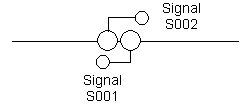
If opposing signals on a bidrectional
line are very close to each other, or mounted on the
same signal post, place the signal nodes as shown. The
spacing between the 2 signals should be 1 column. The
pcol values of the 2 nodes can be adjusted by the required
small amount to line up the bases of the signal posts.
For an example, see Kings Cross signals 290 and 297.
Shunt-only route

Routes S001-S002 and S004-S003 would
be set up in the usual way. If there is no signalled
route to S004, one must be provided to allow
shunt movements. In this case the route would be S002
to S004, with direc = 1, main = True, subsid = False..
|

 Home Page
 Data Values